Networking Fundamentals Study Guide for the CompTIA Network+
Page 3
Cables and Connectors
The cable and connectors are the physical media that are used for data transmission and connection of end devices. You should be familiar with each cable and the connector type each can use, as well as which solution would be appropriate for specific situations.
Copper
Copper is a commonly used medium for data transmission through electromagnetic signals. Copper can be used with solid copper wires, such as in coaxial cables, or in a set of stranded copper wires, such as in Ethernet cables. Each individual copper wire is sheathed in a plastic coating to prevent the copper components from touching other wires.
Twisted Pair
A twisted pair is a set of individual, plastic-coated copper wires that are twisted around one another. The wires are twisted to prevent interference, also called crosstalk, which can occur when electromagnetic signals are transmitted over copper. The twisting of the wires reduces crosstalk as well as protects against outside interference. Twisted pairs can be either a shielded twisted pair (STP), meaning they are encased in a protective metallic shield, or an unshielded twisted pair (UTP). UTP wires are graded based on categories, commonly referred to as “Cat” ratings, which define the number of twisted pairs in the wire as well as the capabilities of the wire.
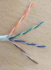
Retrieved from: https://commons.wikimedia.org/wiki/File:Utp_diy02_sequenceInCable.jpg License: http://creativecommons.org/licenses/by-sa/3.0/
Category 5 (Cat 5)—A Cat 5 UTP cable consists of four pairs of wires (eight total) and is used for Ethernet connections. A Cat 5 cable is used for 100BASE-TX Ethernet networks and is rated for 100 MHz with a max Ethernet speed of up to 10 Mbps and 100 Mbps for Fast Ethernet. Cat 5 cables use RJ45 connectors.
Category 5 Enhanced (Cat 5e)—A Cat 5e cable is an STP cable consisting of four pairs of wires. Cat 5e provides superior protection against interference due to the shielding as well as the tightness of the twist. Cat 5e is used for 1000BASE-T Ethernet networks and is rated for 100 MHz and compatible with Ethernet, Fast Ethernet, and 1,000 Mbps Gigabit Ethernet (GbE).
Note: Cat 5e should be the minimum category of cable used in today’s networking environment.
Category 6 (Cat 6)— A Cat 6 cable consists of four twisted pairs, either UTP or STP, and is used in 1000BASE-TX Ethernet connections. A Cat 6 cable is rated for 250 MHz and Gigabit Ethernet as well as 10 Gigabit Ethernet (10 GbE) up to 55 meters. Cat 6 cables are commonly used as a riser cable to connect floors in older installations, or they can be used for all connections in a new build. Cat 6 cables use RJ45 connectors.
Augmented Category 6 (Cat 6a)—A Cat 6a cable consists of four twisted pairs, either UTP or STP, and are designed to reduce crosstalk and to be used for 10GBASE-T connections. A Cat 6a cable is rated for 500 MHz and 10 GbE up to 100 meters. Cat 6a cables use RJ45 connectors.
Category 7 (Cat 7)—A Cat 7 cable consists of four fully shielded twisted pairs rated for 600 MHz and 10GbE up to 100 meters. Cat 7 cables use non-RJ45 connectors.
Category 8 (Cat 8)—A Cat 8 cable consists of four fully shielded twisted pairs rated for 2,000 MHz and 25 GbE or 40 GbE up to 30 meters. Cat 8 cables are most commonly used in data centers. A Class I Cat 8 cable uses an RJ45 connector, while a Class II uses a non-RJ45 connector.
Coaxial/RG-6
Coaxial, commonly referred to as coax cable, is a solid strand of copper surrounded by a plastic jacket with a braided shield over the top of the entire cable. The most commonly used plastic sheathing is polyvinyl chloride (PVC) and fluoroethylene propylene (FEP). FEP, commonly known as Teflon™, is plenum-rated because it resists fire and does not release hazardous chemicals into the air if burnt. Safety requirements specify that cable running in the plenum, the space between floors of a building, must be plenum-rated. The most commonly used type of coax cable is radio-rade 6 (RG-6), which is designed for cable TV and cable modem transmissions but is not suitable for direct Ethernet connections. An RG-6 cable typically uses an F-type connector.
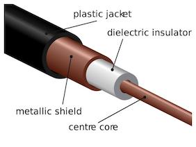
Retrieved from: https://commons.wikimedia.org/wiki/File:Coaxial.svg License: http://creativecommons.org/licenses/by-sa/3.0/
Twinaxial
A twinaxial cable is similar to traditional coax except that it contains two copper conductors in a twisted pair instead of one. Twinaxial cable is able to deliver up to 10 GbE connections over a short distance at a lower cost than fiber.
Termination Standards
A termination standard is how a cable is configured at its endpoints. Twisted pairs end in an RJ45 connector, which places each stand in the cable into a specific spot depending on which termination standard is being used. The wires in twisted pairs follow a standardized color coding where one wire is a solid color and its pair is a mix of that color and white. The four pair colors are green and green/white, blue and blue/white, orange and orange/white, and brown and brown/white. The termination standards are accredited by the American National Standards Institute (ANSI) and was established by the Electronic Industry Alliance’s (EIA) communications sector, also known as the Telecommunications Industry Association (TIA).
Note: While the EIA has since been dissolved, the standards for the interconnection of electronic components are still designated as EIA standards by ANSI. Some newer publications refer to these standards as ANSI/TIA instead of TIA/EIA, but the latter naming convention is still the most common.
TIA/EIA-568A—The TIA/EIA-568A termination standard pattern is green/white, green, orange/white, blue, blue/white, orange, brown/white, brown.
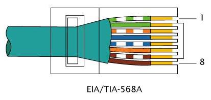
Retrieved from: https://commons.wikimedia.org/wiki/File:RJ-45_TIA-568A_Right.svg License: http://creativecommons.org/licenses/by-sa/3.0/
TIA/EIA-568B—The TIA/EIA-568B termination standard pattern is orange/white, orange, green/white, blue, blue/white, green, brown/white, brown.
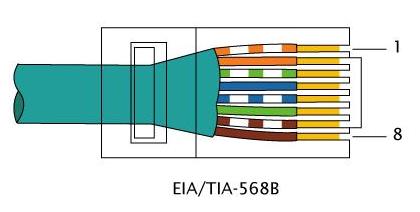
Retrieved from: https://commons.wikimedia.org/wiki/File:RJ-45_TIA-568B_Right.svg License: http://creativecommons.org/licenses/by-sa/3.0/
When creating cables, a straight-through cable will have the same termination standard on both ends, while a crossover cable will have one termination on one end and the other termination standard on the other.
Fiber
Fiber (or fiber-optic) cables transmit data via light pulses sent over a glass or plastic core. The core glass or plastic is surrounded by a glass or plastic cladding that reflects the light pulses back into the core cable. This is then wrapped in a flexible plastic buffer. The entire cable can then be wrapped in another protective layer, commonly Kevlar, which can then also be sheathed with PVC or FEB. Fiber cable can be either single or multimode. It is immune to electromagnetic interference (EMI) and radio frequency interference (RFI) and capable of carrying signals quickly over distances up to 40 kilometers. Fiber is, however, more difficult to install, harder to troubleshoot, and more expensive than other cabling types. Fiber uses either a straight tip connector or subscriber connector.
Single-Mode
A single-mode fiber-optic (SMF) cable consists of a single glass fiber (sometimes two) that transmits data from the light source, either light-emitting diodes (LEDs) or lasers, via a pulsed light. SMF is capable of transmitting data extremely quickly over long distances, up to 40 kilometers.
Multimode
Multimode fiber-optic (MMF) cable can be either glass or plastic and uses the light source to disperse a single on multiple paths within the core. MMF has an effective distance of only around 500 meters.
Connector Types
The connector type refers to the attachment on the termination point of a cable, which allows for connection to an end device. Connector types differ depending on the type of cable used.
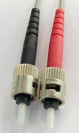
Straight Tip (ST)
An ST connector is a fiber connection type, developed by AT&T, that uses the Bayonet Neill-Concelman (BNC) attachment method to secure a fiber to a device. The BNC attachment method allows for a quick connection that secures itself through an insert-and-twist design.
Retrieved from: https://es.m.wikipedia.org/wiki/Archivo:ST-optical-fiber-connector-hdr-0a.jpg License: http://creativecommons.org/licenses/by-sa/3.0/
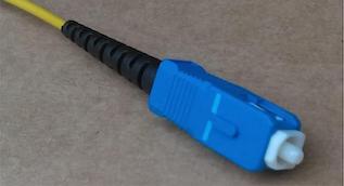
Subscriber Connector (SC)
An SC is a fiber connection type that uses a latching device to secure a fiber to a device.
Retrieved from: https://commons.wikimedia.org/wiki/File:Connectique_fibre_optique_SC!PC_(Switching_Connector_!_Physical_Contact).jpg License: http://creativecommons.org/licenses/by-sa/3.0/
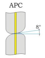
angled physical contact (APC)—An APC is a fiber connector that has an angled physical endpoint, also known as the ferrule. The type of contact the fiber cable makes will impact how much light is lost (also known as reflectance, back reflectance, or optical return loss) during transmission as measured in decibels (dB). APC reflectance loss is -60 dB.
Retrieved from: https://th.m.wikipedia.org/wiki/%E0%B9%84%E0%B8%9F%E0%B8%A5%E0%B9%8C:APC2.png License: http://creativecommons.org/licenses/by-sa/3.0/
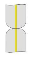
ultra-physical contact (UPC)—A UPC is a fiber connector that has a convex end polish that creates higher reflectance (-40 dB to -50 dB) than an APC polish.
Retrieved from: https://th.m.wikipedia.org/wiki/%E0%B9%84%E0%B8%9F%E0%B8%A5%E0%B9%8C:APC2.png License: http://creativecommons.org/licenses/by-sa/3.0/
Mechanical Transfer (MT)
A mechanical transfer (MT) connector is a multifiber connector, commonly used with RJs, that houses fiber pairs with locating pins. The MT-RJ fiber connector is an SMF connector with two fiber pairs that have their locating pins on the plug and have a male-female configuration.
Registered Jack (RJ)
An RJ connector is a standardized connection method used most commonly for Ethernet connections. There are multiple RJ configurations that specify how the wires are placed within the connector, such as RJ45.
RJ11
An RJ11 connector is commonly used for telephone transmissions and uses a four-pinout layout (how the wires are placed within the connector).
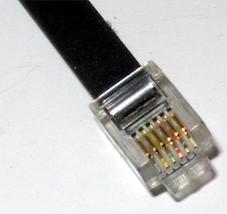
Retrieved from: https://commons.wikimedia.org/wiki/File:Photo-RJ11.jpg License: http://creativecommons.org/licenses/by-sa/3.0/
RJ45
An RJ45 connector houses four pairs of wires and is commonly used with Ethernet twisted pair cables in an eight-pinout layout.
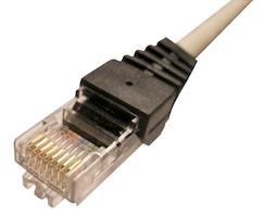
Retrieved from: https://commons.wikimedia.org/wiki/File:Rj45.png License: http://creativecommons.org/licenses/by-sa/3.0/
F-Type Connector
An F-type connector (or F connector) is a connection method that houses the wire inside a connector that can be screwed onto the receiving device to ensure a secure connection. F-type connectors are commonly seen in use with coax cabling and RG-6 connectors.
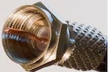
Retrieved from: https://commons.wikimedia.org/wiki/File:F_Connector_Side.jpg License: http://creativecommons.org/licenses/by-sa/3.0/
Transceivers and Media Converters
A transceiver, as relates to physical connection types, is a device that both transmits and receives signals in a single housing or by using common circuitry. A media converter is a device that converts one media type or signal type to another, such as fiber to Ethernet or fiber to coaxial.
Transceiver Type
When referring to copper or fiber connections, a transceiver can come in different configurations with different capabilities.
small form-factor pluggable (SFP)— An SFP transceiver is a compact pluggable hot-swappable optical receiver used with 100BSE or 1000BASE applications over long distances. SFPs can accommodate either copper or fiber and allow for connections to a switch or other networking device. SFPs support two bidirectional links on one interface.
enhanced form-factor pluggable (SFP+)—An SFP+ is similar to an SFP but supports up to 16 Gbps transmissions over a shorter distance.
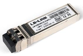
Retrieved from: https://commons.wikimedia.org/wiki/File:LR-Link_10GBASE-SR_SFP%2B_transceiver.jpg License: http://creativecommons.org/licenses/by-sa/3.0/
quad small form-factor pluggable (QSFP)—A QSFP is a compact pluggable hot-swappable optical receiver that can accommodate four links on one interface at gigabit speeds.
enhanced quad small form-factor pluggable (QSFP+)—A QSFP+ is similar to the QSFP but supports 10-gigabit speeds over a shorter distance.
Local Connector (LC)
An LC is an SC small form factor (SFF) connector, which allows for more fiber optic connections in the same space as a traditional connector, which provides gigabit transmissions in an easy-to-install format using a ceramic insert.
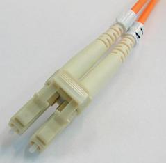
Retrieved from: https://commons.wikimedia.org/wiki/File:LC-optical-fiber-connector-hdr-0a.jpg License: http://creativecommons.org/licenses/by-sa/3.0/
Cable Management
Cable management refers to how cables are organized, routed, and supported in a network. Cable management includes the devices that are used, such as patch panels or punch-down blocks, as well as how cables are organized for component identification and troubleshooting purposes.
Patch Panel/Patch Bay
A patch panel or patch bay is a hardware housing assembly that provides connection ports for the management of incoming and outgoing cables. A patch panel or patch bay is a dumb device that has no networking capabilities by itself but merely acts as a connection point between switches.
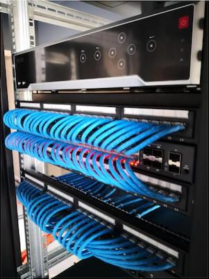
Retrieved from: https://pxhere.com/en/photo/1610246 License: https://creativecommons.org/publicdomain/zero/1.0/
Fiber Distribution Panel
A fiber distribution panel, also known as a fiber enclosure, is a patch panel for fiber optic termination and distribution. A fiber distribution panel provides a tray for cable management as well as a splice drawer for fiber connections.
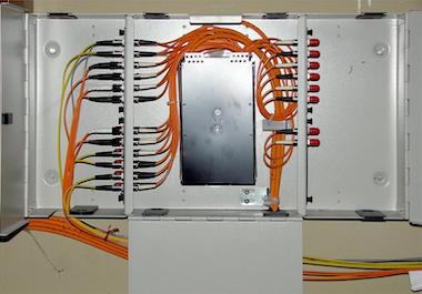
Retrieved from: https://commons.wikimedia.org/wiki/File:Optical-fiber-distribution-frame-0a.jpg License: http://creativecommons.org/licenses/by-sa/3.0/
Punch-down Block
A punch-down block is a cable management device that allows for the connection of different wires through a metal peg system. Punch-down blocks are commonly used for copper wire connections by pushing or “punching down” a wire into one side of the peg connector and another wire on the opposite side, creating a connection between the two.
66—A 66 block is a punch-down block only used with older analog telephone connections. The 66 block uses a 25-pair cable (one cable consisting of 25 individual wire pairs) and 50 rows of terminating points.
110—A 110 block is a punch-down block that can be used for telephone and computer networking by providing punched-down wires on one side and a standard connector type, such as RJ11 or RJ45, on the other. A 110 block can accommodate anywhere from 25 to more than 500 wire pairs, but it is difficult to use with Cat 6 and beyond cables due to the thickness of the wire.
Krone—A Krone block is a proprietary European version of the 110 block that is compatible and interchangeable with US 110 blocks.
BIX—A BIX block is a punch-down block that can house up to 25 pairs without the need to pre-strip the wire before insertion.
Ethernet Standards
Ethernet is a connection method that shares bandwidth between all hosts on a link. Ethernet standards refer to the physical and data link layer specifications as defined in IEEE 802.3 for Ethernet connections. The Institute of Electrical and Electronics Engineers (IEEE) developed a standardization for different Ethernet media and their corresponding properties, functions, and implementations.
Copper
Copper is one medium that can be used for Ethernet connections. Each Ethernet standard defines the type of copper media used as well as the connector type in addition to its transmission capabilities.
10BASE-T—10BASE-T provides 10 Mbps over a Cat 3 UTP cable using an RJ45 connector (also known as an eight-pin modular connector) with a physical star topology or logical bus topology.
100BASE-TX—100BASE-TX (defined in IEEE 802.3u and known as Fast Ethernet) provides 100 Mbps over a Cat 5, 5e, or 6 STP or UTP cable using an RJ45 connector with a physical star or logical bus topology.
1000BASE T—1000BASE-T (IEEE 802.3ab) provides 1000 Mbps over a Cat 5 or higher UTP cable using an RJ45 connector.
10GBASE-T—10GBASE-T (IEEE 802.3an) provides 10 Gbps over a Cat 5e and up UTP cable with an RJ45 connector.
40GBASE-T—40GBASE-T (IEEE 802.3bq) provides 40 Gbps over a Cat 8 UTP cable and is commonly used in data centers.
Fiber
Ethernet can also be run on fiber, with IEEE defining 802.3 standards based on fiber usage. While there are specific 802.3 standards based on the use of fiber, fiber may also be used with some of the previously mentioned implementations and is colloquially referred to as 100BASE-TF.
100BASE-FX—100BASE-FX (IEEE 802.3u) provides 100 Mbps over an MMF fiber-optic cable in a point-to-point topology with ST and SC connectors.
100BASE-SX—100BASE-SX is the Fast Ethernet standard over a fiber-optic cable.
1000BASE-SX—1000BASE-SX (IEEE 802.3z) provides 1,000 Mbps over an MMF fiber-optic cable using short wavelength lasers and SC connectors.
1000BASE-LX—1000BASE-LX (IEEE 802.3z) provides 1,000 Mbps over either an MMF or SMF fiber-optic cable using longer wavelength lasers and SC or LC connectors.
10GBASE-SR—10GBASE-SR provides 10 Gbps over an MMF fiber-optic cable and an 850 nm laser.
10GBASE-LR—10GBASE-LR provides 10 Gbps over an SMF fiber-optic cable and a 1,310 nm laser over a distance of 10 kilometers.
coarse wavelength division multiplexing (CWDM)—CWDM is a bidirectional transmission standard that provides the ability to transmit 18 wavelengths over a single fiber.
dense wavelength division multiplexing (DWDM)—DWDM is a bidirectional transmission standard that provides the ability to transmit over 80 individual wavelengths over a single fiber at speeds higher than CWDM.
bidirectional wavelength division multiplexing (WDM)—Bidirectional WDM uses different wavelengths to transmit multiple signals over a single fiber-optic cable.
All Study Guides for the CompTIA Network+ are now available as downloadable PDFs