Electronics Information Study Guide for the ASVAB
Page 2
Household Electrical Systems
Questions in this area will concern electricity use in a home or business environment, including safety concepts.
AC vs. DC
DC stands for “direct current” and AC stands for “alternating current”.
Direct current is current that flows in only one direction. Alternating current, as its name indicates, alternates in the direction it flows.
Batteries produce DC, but rectifiers and commutators can also generate DC from AC. Alternators produce AC. In an alternator, a wire with a current running through it is rotated inside of a magnetic field. The position of the wire with respect to the direction of the magnetic field produces a current that alternates in direction.
Where DC circuits have resistance, AC circuits have impedance.
The Frequency Equation
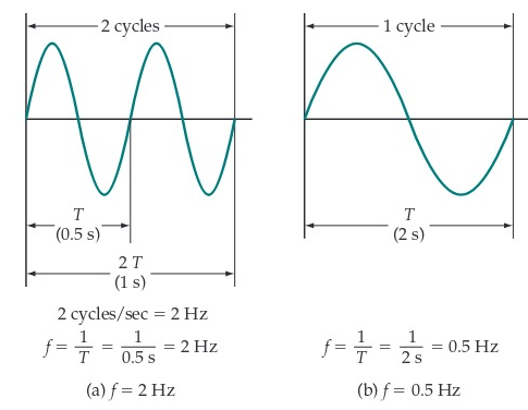
A waveform has a frequency of 1 hertz (Hz) when it goes through one complete cycle of change in a period of one second.
When two complete cycles of the waveform occur in one second, the frequency is two cycles per second or \(2\text{ Hz}\). In this case, the time period of one cycle is \(T = 0.5 \;\text{s}\), and
\[f=\frac{1}{0.5\text{s}}=2\text{ Hz}\]Similarly, if the waveform has a time period of \(2\;\text{s}\), its frequency is one cycle per \(2\;\text{s}\). So,
\[f=\frac{1}{2\text{s}}=0.5\text{ Hz}\]
The frequency of the waveform is always found by inverting the time period:
\[f=\frac{1}{T}\]where f is in hertz and T is in seconds.
The usual (North American) frequency for domestic and industrial AC supplies is 60 Hz. In electronics, the frequencies of ACwaveforms can range from zero (i.e., DC) through kilohertz (kHz), megahertz (MHz), and gigahertz (GHz).
Grounding
Grounding is a method of neutralizing a charged object by connecting it to a much larger source of charge (most commonly the earth). The immense size of the earth enables it to act as a reservoir of charge as well as a reference point with which to compare voltages.
Ground wires provide a low resistance path to the earth and help prevent electric shock in the case of faulty circuits.
Resistors
Resistors are passive circuit components used to reduce current flow and voltage levels in a circuit. They are useful for modifying circuits to produce a desired amount of current.
Resistors come marked with four or five colored bands that signify the amount of resistance (and tolerance) they provide. The last band indicates the tolerance in the resistor, whereas the second to last band represents the multiplier, or what the first two or three bands are multiplied by to find the resistance.
If the resistivity of the resistor’s material is known, the resistance can be found using the following equation:
\[R = ⍴ \cdot \frac{L}{A},\]where \(⍴\) represents the resistivity of the conducting material, L is the length, and A is the cross-sectional area.
Resistors can be used in a circuit in series, in parallel, or in series-parallel fashion. Depending on the type of composition, the equivalent resistance, or resistance for the entire circuit, is calculated in different ways.
Fixed Resistor
A fixed resistor is a resistor that has only one resistance value. The resistance value cannot be changed or adjusted. Fixed resistors include carbon composition, wire-wound, and metal film resistors.
A carbon composition resistor is a resistor made of carbon graphite and clay. A wire-wound resistor is a resistor constructed using various types of wire wounds on an insulating form. A metal film resistor is a type of resistor made up of a metal film of a specific metal alloy or carbon deposited in a vacuum on a small ceramic cylinder to which leads are connected.
Variable Resistor
A variable resistor is one that’s resistance can be changed to any value within its range. When making frequent adjustments, like adjusting the volume on a television set, variable resistors are employed.
The resistance element of variable resistors may be carbon composition, wire-wound, or deposited film. Variable resistors may be low-power or high-power and are manufactured with a wide range of resistance values. Variable resistors can be changed from a resistance of 0 Ω to the stated resistance value of the device.
A potentiometer is essentially a single resistor with terminals at each end and a movable contact that can be set to any point on the resistor. Terminals A and B in the following figure are the end terminals, and terminal C is the adjustable contact. Potentiometers are commonly used as voltage dividers.

A rheostat is a variable resistor with two terminals. Rheostats are current-limiting devices and typically have a power rating over 2 W. Rheostats are used for controlling the light level of incandescent lamps. A potentiometer can be wired as a rheostat if only one end of the resistance element and the movable arm are connected to the circuit. When using a potentiometer as a rheostat, the power rating must be sufficient for the application. Rheostats are often wire-wound and have higher power ratings than potentiometers.
Fuses, Circuit Breakers, and Short Circuits
Fuses and circuit breakers are safety features that preserve the integrity of a circuit in the case of a power overload. Unwanted surges of power in a circuit can have detrimental effects. Consequently, features like fuses and circuit breakers are included as safety switches that will disrupt or break the circuit before any large scale damage is done.
A circuit is shorted when the intended pathway of the current in a circuit is “shorter” than it is designed to be. A short circuit is undesirable because of the surge in current running through the circuit and the possible dangers associated with this surge.
Capacitor and Capacitive Reactance
Capacitors, like resistors and inductors, are passive circuit components. They serve to temporarily store electrical energy in a circuit. When connected to a voltage source, a conductor becomes charged. The voltage source can then be disconnected, and the capacitor functions similarly to a battery in that it can discharge and provide energy to a circuit.
Capacitors are made of two conducting plates separated by a distance containing a dielectric (a material that can become polarized). Much like resistance can be calculated for resistors, capacitance can be calculated for capacitors:
\[C = \frac{Q}{V}\]where C is capacitance, Q is charge, and V is voltage.
Capacitance is measured in farads.
In response to the frequency produced in an AC circuit, capacitors have an impedance that is known as capacitive reactance. This reactance can be calculated using the formula:
\[X_c = \frac{1}{\omega C}\]where \(\omega\) is the angular frequency and C is the capacitance.
Semiconductors and Doping
Semiconductors are components that can function as either an insulator or a conductor. Silicon and germanium are the most commonly used semiconducting materials. Unlike conductors, semiconductors increase in conductivity when their temperature increases.
Diodes and transistors are both examples of semiconductors.
Doping is the process of adding impurities (in the form of extra or absent electrons) to a semiconducting material as a means of altering its electrical properties. Through doping, a semiconductor can become more or less conductive.
Diodes
A diode is formed by joining N- and P-type semiconductor materials together, as illustrated in the following figure. Where the materials come in contact with each other, a junction is developed. This device is known as a junction diode. Diode leads are identified as the anode lead (connected to the P-type material) and the cathode lead (connected to the N-type material).

Diodes are electrical components that restrict the movement of current to only one direction and block the motion of current in the opposite direction. They are used in bridge rectifiers to convert AC to DC.
Forward-biased—The diode is considered to be forward-biased when the polarity of the battery allows electrons to flow freely through it.
Reverse-biased—The diode is described as reverse-biased when the polarity of the battery prevents electrons from flowing through it.

Anode/Cathode—To make the circuit forward-biased, connect the positive terminal of the battery to the P-type material (also identified as the anode) and the negative terminal of the battery to the N-type material (also recognized as the cathode).
Rectification—The most important application of diodes is rectification. It is an important part of the process of converting an AC signal to a direct current, which is the process of converting an electrical signal so that all of its parts have the same sign. Of particular interest is the process of converting an AC signal (e.g., a typical 120-V rms line voltage) with zero average (DC) value to a signal with a nonzero DC value. For example, power supplies use rectification to produce a DC output from the readily available AC line voltage.
A half-wave rectifier is an electrical circuit that consists of an AC source, a load resistor, and a diode that allows only the positive half cycles of the alternating current sine wave to pass, resulting in pulsating DC.
A full-wave rectifier is an electrical circuit that uses two diodes and a center-tapped transformer to generate pulsating DC.
Transistors
Transistors are three-terminal semiconductor components used to regulate current and voltage in a circuit. They can amplify current and act as electrical switches.
Solid-state device—Solid-state refers to the use of a solid material to control electrons or electron flow. The transistor is a solid-state device that is made from solid silicon.
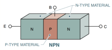
NPN transistor—An NPN transistor is made up of a thin layer of P-type material sandwiched between two layers of N-type material.

PNP transistor—A PNP transistor is made up of a thin layer of N-type material sandwiched between two layers of P-type material.

Base—The base is the region between the collector and the emitter and acts as a trigger for high emitter-to-collector current.
Collector—The charge carriers are drawn to the collector region. The current flows from the emitter to the collector and then out from the collector.
Emitter—The emitter emits charges into the collector through the base.
All Study Guides for the ASVAB are now available as downloadable PDFs