Formulas for the ASVAB Mechanical Comprehension Test
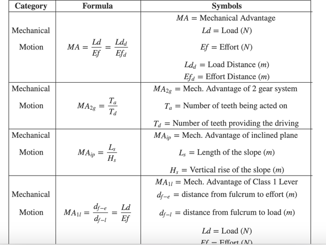
Working with tanks, repairing aircraft, being in charge of a submarine engine… it all sounds great, right? If you want to work in mechanical-related jobs in the armed services, you’ll need to ace the ASVAB Mechanical Comprehension Test, and we have the best tools to help you reach your goal, starting with the following formula chart.
You won’t be able to use the formula chart during the test, but it will help you summarize all the relevant information and content you’ll need to know. Try to use it to solve the sample tests, and delve deeper into each formula by consulting our free ASVAB study prep, which includes study material for the Mechanical Comprehension Test.
Principles of Mechanical Devices
| Formula | Symbols | Comment |
|---|---|---|
| \(f = m \cdot a\) | \(f = \text{force }(N)\) \(m = \text{mass }(kg)\) \(a = \text{acceleration } (m/s^2)\) |
|
| \(w = f \cdot x\) | \(w = \text{work }(J)\) \(f = \text{force }(N)\) \(x = \text{displacement } (m)\) |
|
| \(P E_g= m \cdot g \cdot h\) | \(P E_g = \text{Gravitational Potential Energy }(J)\) \(m = \text{mass }(kg)\) \(g = \text{gravity } (m/s^2)\) \(h=\text{height }(m)\) |
|
| \(KE = \dfrac{1}{2} \cdot m \cdot v^2\) | \(KE = \text{Kinetic Energy }(J)\) \(m = \text{mass }(kg)\) \(v = \text{velocity } (m/s)\) |
|
| \(w = KE_f - KE_i\) | \(w = \text{work }(J)\) \(KE_f = \text{Final Kinetic Energy }(J)\) \(KE_i = \text{Initial Kinetic Energy } (J)\) |
|
| \(E_t=PE +KE\) | \(E_t = \text{Total Energy }(J)\) \(PE = \text{Potential Energy }(J)\) \(KE = \text{Kinetic Energy } (J)\) |
In cases where there aren’t any nonconservative forces. |
| \(E_t = PE + KE + w_{ex}\) | \(E_t= \text{Total Energy }(J)\) \(PE = \text{Potential Energy }(J)\) \(KE = \text{Kinetic Energy } (J)\) \(w_{ex} = \text{Work by a nonconservative force } (J)\) |
In cases where there is a nonconservative force. |
| \(p = \dfrac{w}{t}\) | \(p = \text{power }(W)\) \(w = \text{work }(J)\) \(t = \text{time } (s)\) |
|
| \(F_g = G \cdot \dfrac {m_1 \cdot m_2}{r^2}\) | \(F_g = \text{Force of Gravity }(N)\) \(G = \text{Gravitational Constant }(Nm^2/kg^2)\) \(m_n = \text{mass n } (kg)\) \(r = \text{distance }(m)\) |
|
| \(F_f = \mu \cdot F_n\) | \(F_f = \text{Friction Force }(N)\) \(\mu = \text{Friction Coefficient }\) \(F_n = \text{Normal Force } (N)\) |
|
| \(F_s = k \cdot x\) | \(F_s = \text{Compression Force of Spring }(N)\) \(k = \text{Spring constant }(N/m)\) \(x = \text{displacement of the spring } (m)\) |
|
| \(F_t = m \cdot g\) | \(F_t = \text{Tension Force }(N)\) \(m = \text{mass }(kg)\) \(g = \text{gravity } (m/s^2)\) |
Mechanical Motion and Fluid Dynamics
| Formula | Symbols |
|---|---|
| \(MA = \dfrac{Ld}{Ef} = \dfrac{Ld_d}{Ef_d}\) | \(MA= \text{Mechanical Advantage }\) \(Ld = \text{Load }(N)\) \(Ef = \text{Effort } (N)\) \(Ld_d = \text{Load Distance }(m)\) \(Ef_d = \text{Effort Distance }(m)\) |
| \(MA_{2g} = \dfrac{T_a}{T_d}\) | \(MA_{2g} = \text{Mech. Advantage of 2 gear system }\) \(T_a = \text{Number of teeth being acted on }\) \(T_d = \text{Number of teeth providing the driving }\) |
| \(MA_{ip} = \dfrac{L_s}{H_s}\) | \(MA_{ip} = \text{Mech. Advantage of inclined plane }\) \(L_s = \text{Length of the slope }(m)\) \(H_s = \text{Vertical rise of the slope }(m)\) |
| \(MA_{1l} = \dfrac{d_{f-e}}{d_{f-l}} = \dfrac{Ld}{Ef}\) | \(MA_{1l} = \text{Mech. Advantage of Class 1 Lever}\) \(d_{f-e} = \text{distance from fulcrum to effort }(m)\) \(d_{f-l} = \text{distance from fulcrum to load }(m)\) \(Ld = \text{Load }(N)\) \(Ef = \text{Effort }(N)\) |
| \(MA_{2l} = \dfrac{d_e}{d_l}\) | \(MA_{2l} = \text{Mech. Advantage of Class 2 Lever }\) \(d_e = \text{effort distance }(m)\) \(d_l = \text{load distance }(m)\) |
| \(MA_{3l} = \dfrac{Ld}{Ef}\) | \(MA_{3l} = \text{Mech. Advantage of Class 3 Lever }\) \(Ld = \text{Load }(N)\) \(Ef = \text{Effort }(N)\) |
| \(MA_{sc} = \dfrac{d_e}{d_l} = \dfrac{2 \cdot \pi \cdot l}{d_l}\) | \(MA_{sc} = \text{Mech. Advantage of a screw }\) \(d_e = \text{effort distance }(m)\) \(d_l = \text{distance traveled by the screw in 1 turn }(m)\) \(l= \text{length of the tool used to rotate the screw }(m)\) \(\pi \approx 3.14\) |
| \(MA_{wd} = \dfrac{l_{wd}}{w_{wd}}\) | \(MA_{wd} = \text{Mech. Advantage of a wedge }\) \(l_{wd}= \text{wedge length }(m)\) \(w_{wd} = \text{wedge width }(m)\) |
| \(P = \dfrac{f}{a} = \rho \cdot g \cdot h\) | \(P = \text{Pressure }(Pa)\) \(f = \text{force }(N)\) \(a = \text{area }(m^2)\) \(\rho = \text{density of gas or fluid }(kg/m^3)\) \(g = \text{gravity }(m/s^2)\) \(h = \text{height of the column of gas or fluid }(m)\) |
| \(MA_{hl} = \dfrac{D_1}{D_2} = \dfrac{A_2}{A_1}\) | \(MA_{hl} = \text{Mech. Advantage of Hydraulic Lift }\) \(D_n = \text{Distance traveled by cylinder n }\) \(A_n = \text{Cross sectional are of cylinder n }\) |
| \(r_f = \dfrac{v}{t}\) | \(r_{f} = \text{flow rate }(m^3/s)\) \(v = \text{volume }(m^3)\) \(t = \text{time }(s)\) |
Keep Reading

Armed Services Vocational Aptitude Battery Blog
What is the ASVAB Test?
The Armed Services Vocational Aptitude Battery, known as the ASVAB, is …

Armed Services Vocational Aptitude Battery Blog
Military MOS Codes
Military Occupational Specialty (MOS) codes are an integral part of the…

Armed Services Vocational Aptitude Battery Blog
U.S. Army Height and Weight Standards for Females
The U.S. Army’s commitment to maintaining a robust, physically fit, and…